Product Details
- Low insertion loss: 0.79dB at 2GHz
- High isolation:
- 71dB at 1GHz
- 65dB at 2GHz
- 58dB at 4GHz
- High IIP3: +65dBm at 2.6GHz
- Supply voltage: +2.7V to +5.5V
- 1.8V and 3.3V compatible control logic
- Operating temperature: -40°C to +110°C
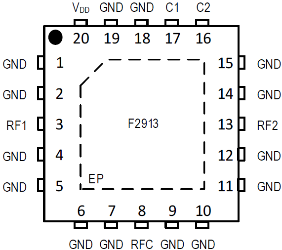
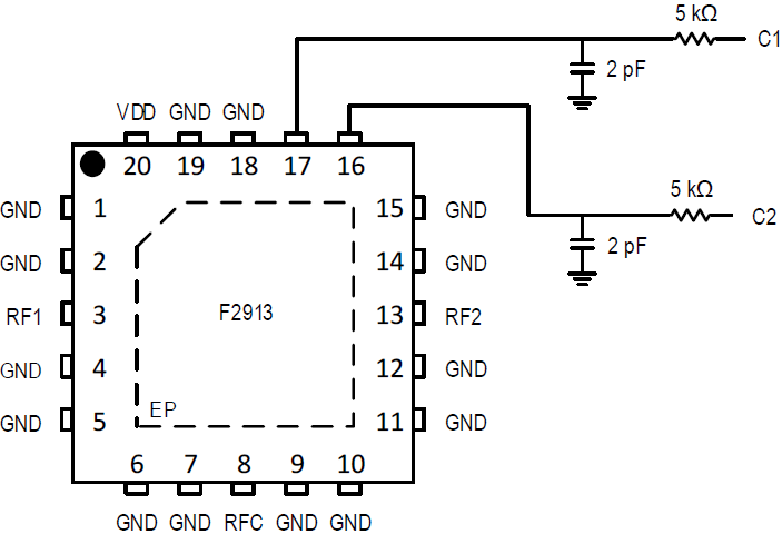
- 4 × 4mm 20-QFN package
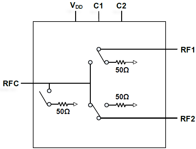
The F2913 is a high isolation, low insertion loss, 50? SPDT (SP2T) absorptive RF switch designed for a multitude of wireless and RF applications. This device covers a broad frequency range of 50MHz to 6000MHz. In addition to providing low insertion loss, the F2913 also delivers high linearity and high isolation performance while providing a 50? termination at all RF ports. The F2913 uses a single positive supply voltage of +2.7V to +5.5V and supports three states using either +1.8V or +3.3V control logic.
Product Documents
Type
Name
Date
Actions
2025-08-25
F2913 Datasheet
2025-08-25
RF Switches Family
2025-08-25
F2913 S-par
2025-08-25
IDT Products for Wired Broadband Applications
2025-08-25
PCN# : TB1904-03 Add Sigurd Taiwan as Alternate Test Location| F2913NLGK(8)
2025-08-25
PCN# : TB1912-02 Convert Shipping Media from Tube or Tray to Cut Reel
2025-08-25
PCN# : TB1912-02(R1) Convert Shipping Media from Tube or Tray to Cut Reel
Boards and Kits
.png)
Evaluation Board for F2913 High Isolation SPDT Absorptive Switch
The F2913EVBI is a fully populated evaluation board, enabling easy RF evaluation of the product.
“Thru” calibration connectors are conveniently located on the evaluation board to simplify the calibration process prior to making any RF measurements. The RF through measurement (RF1 to RF2) can be made by applying the correct control logic voltage to the control pins as outlined in the datasheet. DC power, ground and the control voltages are applied to the pin header.
Part Number (2)
F2913NLGK
F2913NLGK8
Do you have more questions?
We're here to help you explore possibilities, optimize performance, and drive technological advancements. Reach out today!
Talk to Sales